

By Plinio Guzman
Department of Mechanical Engineering
State University of New York, Stony Brook
Stony Brook, NY 11767
Email: plinio.guzman@stonybrook.ed
By Wusi Chen
Department of Mechanical Engineering
State University of New York, Stony Brook
Stony Brook, NY 11767
Email: wusi.chen@stonybrook.edu
Ya Wang
Department of Mechanical Engineering
State University of New York, Stony Brook
Stony Brook, NY 11767
Email: ya.s.wang@stonybrook.edu
By Lei Zuo
Department of Mechanical Engineering
State University of New York, Stony Brook
Stony Brook, NY 11767
Email: lei.zuo@stonybrook.edu
ABSTRACT
This paper presents the design, modeling and experimental analysis of an amplification frame for a piezoelectric stack to be used in a floor tile energy harvesting device. The proposed energy harvester captures the kinetic energy that a footstep carries as it strikes the ground and converts it into usable DC power. The device can be used in urban areas that are heavily trafficked by pedestrians in order to provide a localized, alternative power supply, ultimately reducing the power requirements from the grid. The system was modeled using Single Degree Of Freedom (SDOF) and Finite Element Method (FEM), and to predict output voltage. Experimental results show a strong correlation with theoretical models and validate their accuracy. As a proof of concept, the energy harvesting performance of the amplified piezoelectric stack was also compared to that of the piezoelectric stack without the use of the frame. A considerable increase in performance proves the design of the amplification frame to be successful.
1 INTRODUCTION
Scavenging energy from ambient vibrations has gained popularity in recent years due in part to the growing concern for clean energy generation [1]. Particular emphasis has been placed on the use of piezoelectricity to convert mechanical to electrical energy [2-4]. One such method, which is the subject of study of this paper, uses a piezoelectric ceramic multilayer stack operating in the d33 mode in order to generate energy from an impact force [5].
The proposed floor tile energy harvester can be placed on the ground as a regular floor tile would be, but has the ability to capture the kinetic energy carried in a footstep and convert that energy into electric power. This device can act as a localized energy source, which can be used to power nearby electronic devices. Ultimately, the energy harvesting system includes a power conditioning unit and a super capacitor in order to store the generated electric power, as shown in Figure 1.
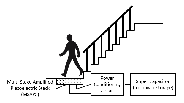
Figure 1 Floor tile energy harvesting system.
This paper presents the design, modeling, and testing of an amplified piezoelectric stack. Two modeling approaches, Single Degree Of Freedom (SDOF) and Finite Element Method (FEM), are used to model the system and predict the voltage and power output of the device. Experimental testing is used to validate the accuracy of these models.
2 DESIGN
Piezoelectric stacks generate relatively low amounts of energy under direct loading due to their high stiffness. This issue is assessed using a frame which is designed to sustain, amplify, and transmit a load onto a piezoelectric stack in a controlled manner.
Piezoceramics are able to bear relatively large compressive stresses, but tend to be weak when under tension, which is why the frame has an auxetic shape that compresses the stack when it receives a load. Its simple kinematic design allows for an indirect transmission of an impact force from the top of the frame to a compressive force on the piezoelectric stack, as shown in Figure 2. An additional advantage of the design is that the links on the frame operate only in tension when a force is applied, which eliminates the concern for buckling. A computer generated model of the amplification frame appears in Figure 3.

Figure 2 Diagram of amplification stack.

Figure 3 Computer generated model of amplification frame.
The frame ensures that the input load is always applied indirectly onto the stack in a predictable manner and in an axial direction. Guaranteeing that strain occurs axially in the active direction of the stack prevents shear (piezoceramics tend to be brittle) and maximizes energy conversion by having the mechanical deformation occur in the direction of the generated electric field.
The flexible frame also acts as a shock absorber which can prevent against sudden extreme loads that might damage the stack. Furthermore, using a customized frame allows the stack to be used in a variety of applications, as it acts as an interface with the environment. This also opens the possibility of using multiple frames in conjunction with an energy harvesting system.
2.1 Stress Analysis
Energy storage within the frame at the moment of impact reduces the energy transfer efficiency. Of all the parts of the frame, the links are the most prone to store energy due to their relatively higher flexibility. Thicker links allow for less bending and for reduced energy storage, and thus make for a stiffer overall frame. The links used in this particular design have a thickness of 0.762 mm and are oriented at 6̊ from the horizontal. A Von Mises stress analysis of the frame under a load of 30 N (6.7 lbf) appears in Figure 4.
The ideal version of the mechanism has rigid links connected with a pivot, resulting in no potential energy within the frame. In this case, no potential energy is stored within the frame and the amplification ratio becomes a function of the geometrical shape only. However, this is not the case. Variations in the frame design are considered throughout the project, and experimental and theoretical comparisons are done with the intent of optimizing the design.

Figure 4 Von Mises stress analysis frame under a load of 30 N (6.7 lbf). Deformation of the frame is exaggerated for illustrative purposes.
3 MATHEMATICAL MODELING
Theoretical models for predicting the energy output of the system are derived through the methods of SDOF and FEM. Two electromechanical equations of motion are derived from the -33 mode constitutive equations, each one describing the physical and the electrical system. The derived SDOF and FEM state space equations are simulated with MATLAB and are solved using the input force signal obtained during the experiment.
3.1 Kinematic Analysis of Input Force
A force analysis of the frame is performed in order to determine the relationship between the force input on the frame and the force transferred onto the stack. A free body diagram of the upper left link of the frame appears in figure 5.

Figure 5 Free body diagram of upper left link.
In the free body diagram (Figure 5) the two ends of the link are labeled 1 and 2. is the angle of the link to the horizontal. is the length of the link. is the force applied on the top of the harvester by a would-be footstep. Due to the symmetric configuration, is applied at point 2. and are forces in the horizontal and vertical direction at joint point 1, is the force in the horizontal direction at point 2. The dynamic equations of the link can be expressed according to Newton’s Law.
Rearranging equations and , can be expressed as
The free body diagram of the block on the left end of the piezoelectric stack is shown in Figure 6. Due to its relatively low displacement, it is assumed to be in the state of dynamic equilibrium.
: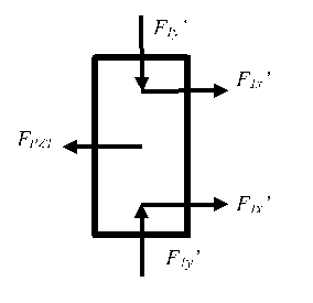
Figure 6 Free body diagram of the left block.
and are the reaction forces of and , respectively. is the reaction force from the left end of the piezoelectric stack. The dynamic equation of the block can be expressed as
FPZT’ can be determined from Eqn. .
The free body diagram of the piezoelectric stack is shown in Figure 7. The piezoelectric stack is assumed to be in a state of equilibrium.
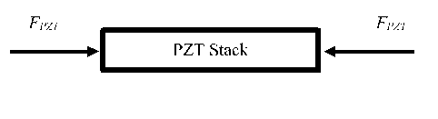
Figure 7 Free body diagram of the PZT stack.
As shown in Figure 6, the input force on the piezoelectric stack is the sum of the forces applied to both ends, and is expressed as
.
The calculated force received by the piezoelectric stack is used to predict the voltage and power output of the system through the derived electromechanical governing piezoelectric equations. The force signal obtained during the experiment is input as a variable in this function in order to model the system’s behavior throughout the duration of the impact.
3.2 Mathematical Modeling of the Constitutive Piezoelectricity Equations
The electromechanical governing piezoelectric equations combine the effect of the electrical behavior of the stack
where D is the electric charge density displacement, is the permittivity, and E is the strength of the electric field, and Hooke’s Law
where S is the mechanical strain, s is the elastic compliance constant and T is the stress. Combined, they constitute the coupled constitutive equations, which for a piezoelectric stack operating under the d33 mode result in the form
In order to predict the voltage output of the system, the constitutive equations are analyzed through both FEM and SDOF in state space form. Derivations of each analysis are omitted from the paper for simplicity. Both models are simulated with MATLAB using the force signal obtained during the experiment. The predicted results appear alongside those obtained experimentally in the results section.
4 EXPERIMENTAL VALIDATION
4.1 Manufacturing of Amplification Frame
The Amplification Frame is made of Impact-Resistant A516 Carbon Steel. It was manufactured through a Wire Electrical Discharge Machining process at Stony Brook University. The finished frames appear in Figure 8.
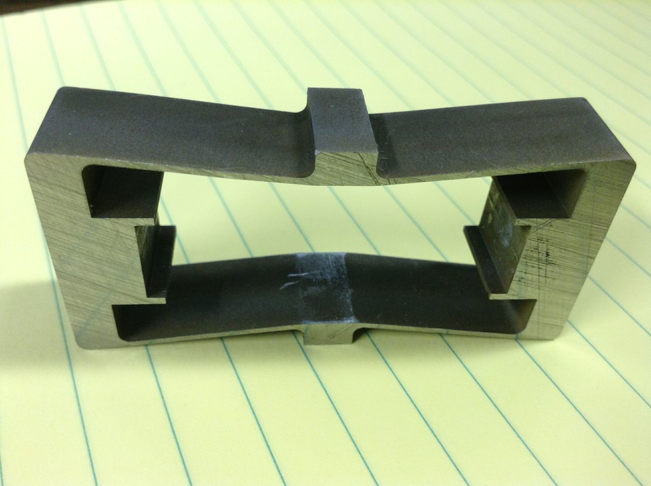
Figure 8 Steel Amplification Frame
4.2 Experimental Setup
The piezoelectric stack used in this study is a P 25/10 stack type actuator manufactured by piezosystems jena. Its physical, electrical and electromechanical properties appear in Table 1.
| Property | Symbol | P-113-00
|
| Cross-sectional area (m2) | A | 7.85e-5 |
| Length (m) | L | 42e-3 |
| Length of the piezo stack (m) | Lactive | 27e-3 |
| Stack mass (kg) | mstack | 2.64e-2 |
| Density (kg/m3) | ρ | 8000 |
| Layer thickness (m) | h | 100e-6 |
| Number of layers | n | 250 |
| Capacitance (F) | C | 2.6e-6 |
| Elastic constant (m2/N) | 18.1e-12 | |
| Dielectric constant (F/m) | 4.82e-8 | |
| Piezoelectric constant (m/V) | 635e-12 | |
| Stiffness (N/μm) | 28 |
Table 1 Properties of P 25/10 stack type actuator.
The piezoelectric stack is placed in the frame, as shown in Figure 9. It is preloaded using the frame’s flexibility so as to minimize energy storage within the frame and ensure full contact. Its two external electrodes are connected in parallel with an Elenco Electronics RS-500 resistor substitution box and a National Instruments NI USB-6212 BNC Data Acquisition (DAQ) board in order to measure output voltage. The resistance on the RS-500 resistor substitution box is adjusted in order to match the source and load impedances in order to optimize the power output [5].

Figure 9 Stack in Amplification Frame
Similarly, a PCB Piezotronics 086C03 impact hammer is connected to the DAQ board with the intention of providing a measurable impact force. The setup allows for the top of the frame to be struck with the hammer and for the output voltage and power of the piezoelectric stack to be recorded and analyzed in a computer.
The voltage output of the stack is obtained through a resistive load and acquired by the DAQ board. In the same manner, the applied force is measured by the hammer’s force sensor as a voltage signal, which is processed through the signal conditioner and acquired by the DAQ board. The actual force is determined by dividing the output voltage by a factor of 2.25 mV/N as indicated by the hammer’s manufacturer [10]. A photographic and schematic representation of the test setup appears in Figures 10 and 11, respectively.

Figure 10 Photograph of Test Setup
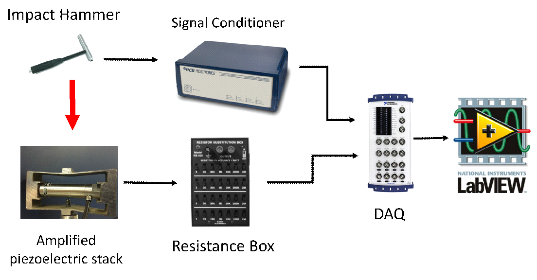
Figure 11 Schematic Representation of Test Setup
4.3 Experimental Procedure
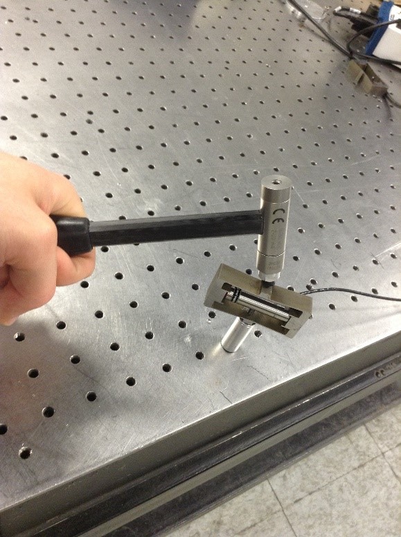
The experiment consists of striking the top of the amplification frame or stack with a vertical motion using the impact hammer, as shown in Figure 12. The setup allows the voltage output of the piezoelectric stack to be related to the force applied with the hammer. Raw data of each test run is recorded with LabVIEW at a sample rate of 1 kHz for a duration of 1 second.
The performance of the amplified piezoelectric stack is compared to both theoretical models and to the performance of the piezoelectric stack without an amplification frame. In order to maximize power output, the source impedance is matched to the load impedance by using a resistive load of 1500Ω in both the experimental setup and in the theoretical calculations.
 With amplification frame
 Without amplification frame
Figure 12 Striking with impact hammer
4.3 Experimental Validation of Theoretical Models
The force signal obtained from the experimental trial, which appears in Figure 13, was used to model the SDOF and FEM systems. The peak magnitude of the signal is 36.73817 N. The voltage and power outputs for each case appear in Figures 14 and 15, respectively. A strong correlation between the experimental results and both model predictions can be observed both numerically and graphically. The peak voltage and power outputs of each case appear in Table 2.
| Magnitude | Percent Error | |
| Vexp (V) | 9.5309 | |
| VFEM (V) | 9.6081 | 4.07% |
| VSDOF (V) | 9.9998 | 0.80% |
| Pexp |
0.0606 | |
| PFEM |
0.0615 | 1.48 |
| PSDOF |
0.0667 | 10% |
Table 2 Peak voltage and power outputs

Figure 13 Force input signal.

Figure 14 Voltage output of FEM, SDOF and experimental cases.

Figure 15 Power output of FEM, SDOF and experimental cases.
4.4 Proof of Concept
As proof of concept, the energy harvesting performance of the piezoelectric stack is studied experimentally with and without the use of the amplification frame. In the first case, a peak input force of 37.46296 N was applied onto the frame, and in the second case, a force of 36.73817 N was applied directly onto the stack. The force signals, voltage output, and power output for each case appear in Figures 16, 17 and 18, respectively. It is determined both graphically and numerically that the voltage and power output of the piezoelectric stack is considerably greater when the amplification frame was used.
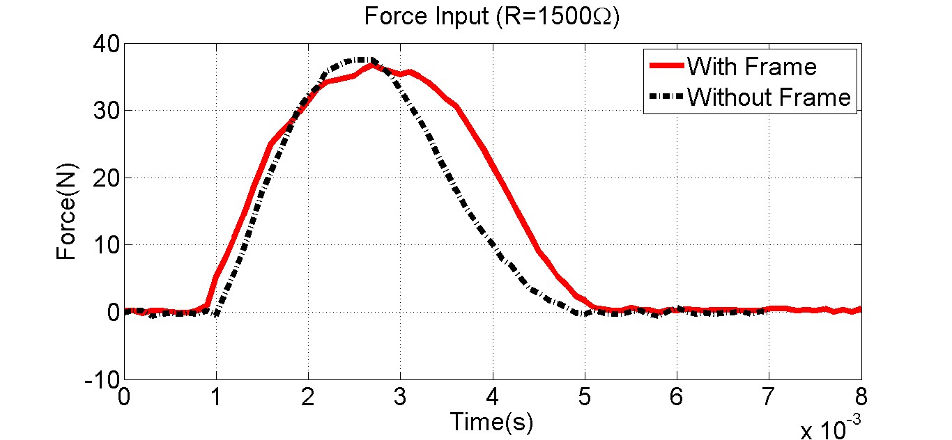
Figure 16 Force input signal

Figure 17 Voltage output of piezoelectric stack with and without amplification frame

Figure 18 Power output of piezoelectric stack with and without amplification frame
5 DISCUSSION
The energy harvesting performance of an amplified piezoelectric stack submitted to an impulse force was analyzed experimentally and through SDOF and FEM modeling. The SDOF and FEM peak voltage outputs vary from the experimentally obtained peak voltage output by 0.80% and 4.07%, respectively. The SDOF and FEM peak power outputs differ from the experimentally determined peak power output by 10.00% and 1.48%. This strong correlation validates the accuracy of the theoretical models of the system, but suggests that room for improvement still exists.
As a proof of concept, the energy harvesting capabilities of the piezoelectric stack were investigated with and without the use of an amplification frame. Data analysis shows a great improvement in performance when the amplification frame is used, proving the design of the frame to be successful.
The frame will be incorporated into a floor-tile energy harvesting system, which will be produced at the Multi-Functional and Adaptive Structures Lab at Stony Brook University.
6 REFERENCES
[1] Wang, Y., and Inman, D.J., 2012, “A Survey of Control Strategies for Simultaneous Vibration Suppression and Energy Harvesting,” Journal of Intelligent Material Systems and Structures, Vol.23, No.18, pp. 2021 – 2037.
[2] Bilgen, O., Wang, Y., and Inman, D. J., 2011, “Electromechanical comparison of cantilevered beams with multifunctional piezoceramic devices,” Mechanical Systems and Signal Processing,Vol.27, pp. 763-777.
[3] Wang, Y., and Inman, D.J., 2013, “Simultaneous Energy Harvesting and Gust Alleviation for a Multifunctional Wing Spar Using Reduced Energy Control via Piezoceramics,” Journal of Composite Materials, Vol. 47, No. 1, pp.125-146.
[4] Wang, Y. and Inman, D.J. 2013, “Experimental Validation for a Multifunctional Wing Spar Design with Sensing, Harvesting and Gust Alleviation Capabilities,” IEEE/ASME Transaction on Mechatronics, Vol. 18, No. 4, pp.1289-1299.
[5] Lee, A.J., Wang, Y., Inman, D. J., 2014, “Energy Harvesting of Piezoelectric Stack Actuator from a Shock Event,” Journal of Vibration and Acoustics, Vol. 136, pp.011016-1-011016-7.
[6] Feenstra, J., Granstrom, J., and Sodano, H., 2008, “Energy Harvesting Through a Backpack Employing a Mechanically Amplified Piezoelectric Stack,” Mech. Syst. Signal Proc., Vol. 22, No.3, pp. 721–734.
[7] Erturk, A., and Inman, D. J., 2008, “On Mechanical Modeling of Cantilevered Piezoelectric Vibration Energy Harvesters,” J. Intell. Mater. Syst. Struct., vol. 19(11), pp. 1311–1325.
[8] F. IEEE Ultrasonics, and Frequency Control Society, 1988, “IEEE Standard on Piezoelectricity,” ANSI/IEEE Standard.
[9] duToit, N. E., Wardle, B. L., and Kim, S., 2005, “Design Considerations for MEMS-Scale Piezoelectric Mechanical Vibration Energy Harvesters,” in Symposium on Ferroelectricity and Piezoelectricity, Cancun, Mexico.
[10] Pcb piezotronics model 086c03. . (2014, January 25). Retrieved from http://www.pcb.com/Products.aspx?m=086C03
[11] M. A. Karami and D. J. Inman, “Powering pacemakers from heartbeat vibrations using linear and nonlinear energy harvesters,”Appl. Phys. Lett., vol. 100, no. 4, pp. 042901-1–042901-4, Jan.
[12] M. Umeda, K. Nakamura, S. Ueha, Energy storage characteristics of a piezo-generator using impact induced vibration, Japanese
Journal of Applied Physics 36(Pt. 1, No. 5B) (1997) 3146–3151.
[13] H.A. Sodano, G. Park, D.J. Inman, Generation and storage of electricity from power harvesting devices, Journal of Intelligent
Material Systems and Structures 16 (1) (2005) 67–75.
[14] Lee, A.J., Wang, Y., Inman, D. J., 2014, “Energy Harvesting of Piezoelectric Stack Actuator from a Shock Event,” Journal of Vibration and Acoustics, Vol. 136, pp.011016-1-011016-7.
